|
Z80 Build From Scratch |
| PAGE 9: Z80 Assembler |
|
Where are we at? We wired the CPU with the data bus tied to ground. This simulated putting 0x00 in every data location as the CPU's Program Counter counted up and chose the next higher address, starting at 0x0000. We attached LEDs via a LED bar graph and termination resistors to the entire address bus, A0 to A15, and confirmed that the CPU was counting upward. This confirmed the CPU's operation.
We removed the data bus tie downs, wired in and programmed the FlashROM to replace the default 0xFF data with 0x00 at every location, and repeated the CPU test. The CPU continued to show the address bus counting upwards due to the No Operation NOPs of 0x00. This confirmed the ROM functionality.
We wired in an SRAM chip and connected a LED bar graph to its data bus. We created a program that would copy data from ROM to RAM and observed the program display on the LED bar graph as well as the 0xF0 0x0F data on the data bus's D0 to D7. We saved the file to our PC so we can quickly pull it up if it's needed in the future. This confirmed the RAM functionality.
What's Next? If we're going to write code it's going to be in assembly language. We'll let the Assembler program convert it to Z80 machine language and save it as a .bin file that we can copy to the FlashROM.
Which Assembler? We like TASM v3.2. TASM v3.2.3 exists - maybe we'll try it out later. Download TASMv3.2.zip and expand it to its own folder where you will keep your source code as well as the .bin files to be copied to the ROM programmer. In the folder you'll find Test_RAM.asm and Assemble.bat that points to it as the source code file. Double-click Assemble.bat which will invoke a Windows DOS cmd window showing the progress as the source code is assembled into machine code. Within this DOS-like window you're looking for "Number of errors = 0". If you right-click Assemble.bat you can edit it in Notepad to see the command string as well as the source and destination file names, .asm and .bin.
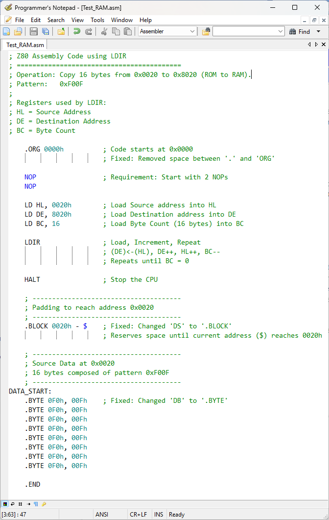
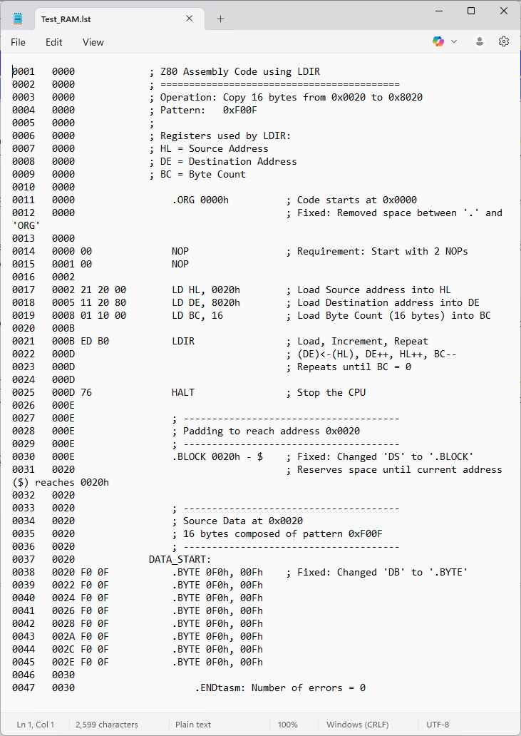
Compare Source .asm to Listing .lst: Now that the file has assembled you can use your text editor(s) to compare Test_RAM.asm to Test_RAM.lst or just click on the thumbnails shown below to enlarge. If you wish to compare them side by side, maybe open each in its own browser window.
Test_RAM.asm and Test_RAM.lst
(Click to enlarge)
The .lst file has individual line numbers which makes it easier to troubleshoot. To the right of the line number is the address location in hex. So line 14 contains address "0000" that contains the machine code "00" which is taken from the next column to the right that contains "NOP", followed by a semicolon ";" that precedes any comments. Are the NOPs needed? No, but I needed to show you the first address as "0002" which you could see on the LED bar graph, "0000" you could not. On line 17 we see the command "21 20 00" at location "0002"; this is our first real command. "LD HL" is the "LOAD" command for register pair "HL" and has a value of "21". It is followed by the location "0020" but in machine language we see it in Little Endian format of "2000" with the lower byte "00" first and the higher byte "20" second. Moving down to line 30 there is a ".BLOCK 0020" command to ensure nothing is written from location "000D" which is the end of the program (command "HALT") until location "0020" where we will put our 16 bytes of "F00F" data we wish to be displayed on the LED bar graph. The ".END" directive on line 47 tells the compiler to cease looking because we've come to the end of the program.
What does the .bin file look like? Download and install HxD and you can examine it for yourself. Here's a screenshot of the contents of Test_RAM.bin.
|

![]()
Updated 2025-11-27