|
Z80 Build From Scratch |
| PAGE 3: Reset Circuit, Pullups |
|
Overview: Any Z80 system must include the following hardware elements: • 5v DC power supply • Oscillator • Reset circuit • CPU • Memory devices • I/O circuits
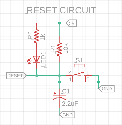
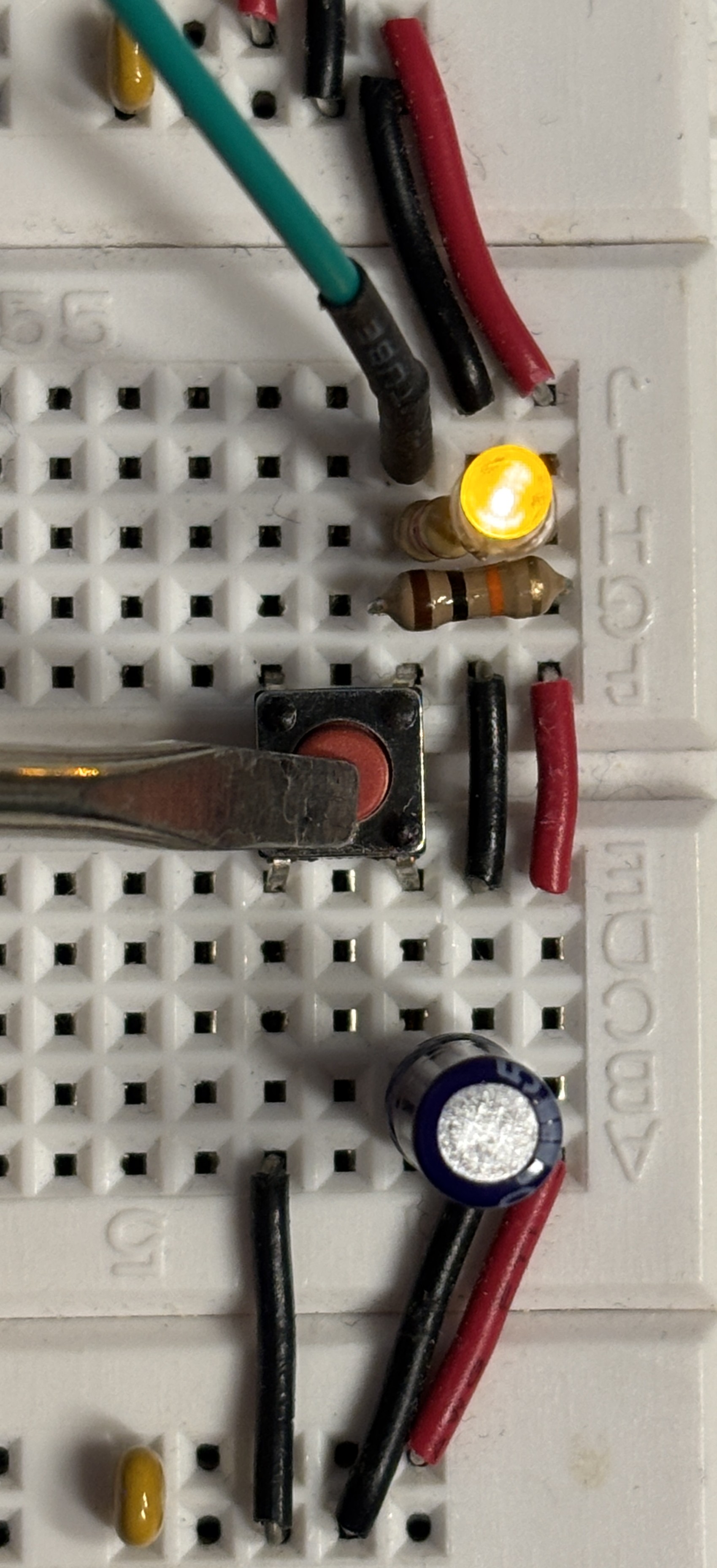
Reset Circuit: We'll build the reset circuit first. We'll add these components to our breadboard as shown in the schematic and photo below. The optional amber LED lets us know we manually activated the reset switch. With the CPU running, holding down the reset switch for at least 3 clock cycles will force a reset and cause the CPU to start looking for code at address 0x0000 (starting ROM location).
Reset Circuit: Schematic and BB
(Click to enlarge )
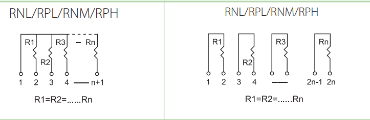
Termination Resistors: All of the control lines are active low (zero volts). Until we need to use them they should be pulled high (5 volts) but we don't want to load down the CPU's limited current budget so we'll use 4.7K ohm resistors. (4.7k or 10k will work for CMOS Z80.) To save space we'll use a 5-pin resistor network SIP pack (one pin to power/GND, 4 individual resistor pins) instead.
Of the 3 images immediately above, the left-most diagram is the one we'll use; it's called a bussed resistor network or SIP. All of the individual 4.7k ohm resistors will be pulled up to 5v (or down to GND in other configurations). The termination point is physically marked with a dot on the left-most pin and represents pin 1 in our diagram. The middle diagram is called an isolated resistor network or SIP and is commonly used to replace a number of individual resistors. We won't use this device just yet. And the right-most image is that of the SIP itself. You'll have to read its labelling to know if its bussed or isolated. Here is a link to the SIPs we'll use.
|

![]()
Updated 2025-11-27