|
Z80 Build From Scratch |
| PAGE 2: Basic Operational Test |
|
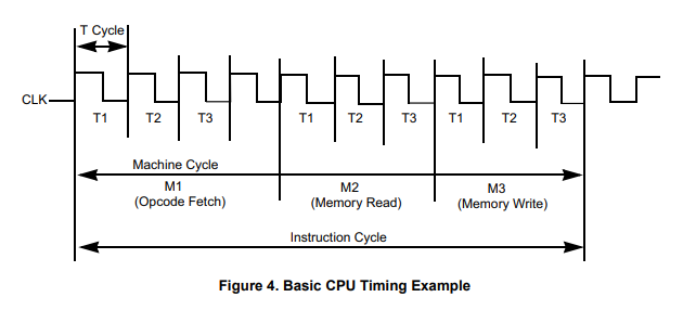
Overview: We have a clock input from either a 555 timer or a dedicated clock board but we don't have any CPU output to tell us if the CPU is working. Let's have a look at page 9 of the Zilog Z80 document, UM0080.pdf. We're interested in the Basic CPU Timing Example diagram shown below. In the Z80 pinout diagram many of the control signals on the left-hand side have a bar above the name, example M1. That means they are active low, either as input or output signals. The fetch cycle of M1 on pin 27 is used to fetch the op code of the next instruction to be executed. Subsequent machine cycles move data between the CPU and memory or I/O devices, and they can feature anywhere from three to five T cycles of the clock (CLK) as shown below.
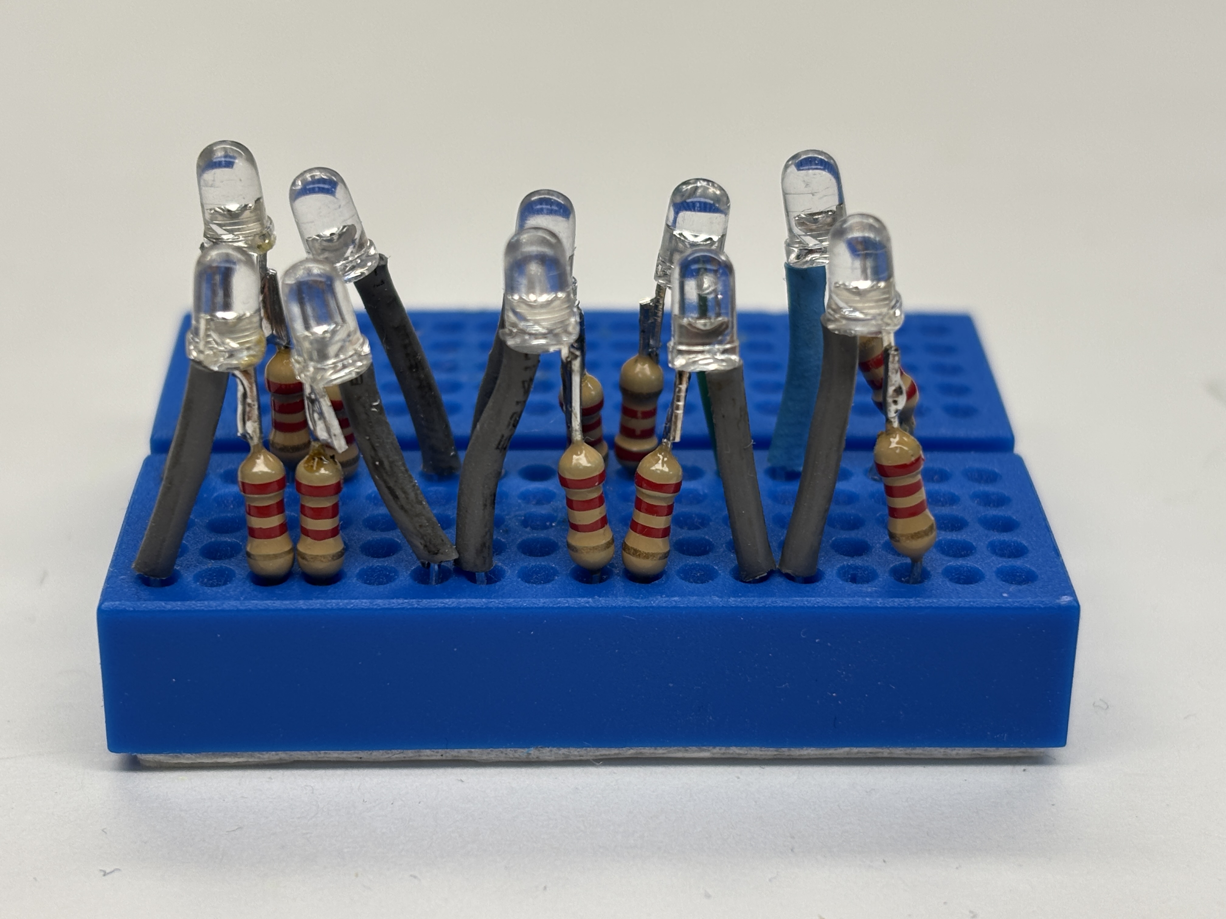
Initial Steps: We'll have a look at the M1 signal on pin 27 by hooking up an LED with at least a 1K resistor attached to it. Normally with LEDs you might use a current limiting resistor between 100 and 330 ohms but that's too much of a load on the Z80 if we use several of them (which we will do later) so we'll try a blue LED with a 2,200 ohm resistor; it won't be bright but it will work. The resistor replaces the cathode (-) side of the LED and we cover the longer anode (+) side with shrink tubing to prevent unexpected surprises. See the image below.
LED and 2.2K Resistor Device
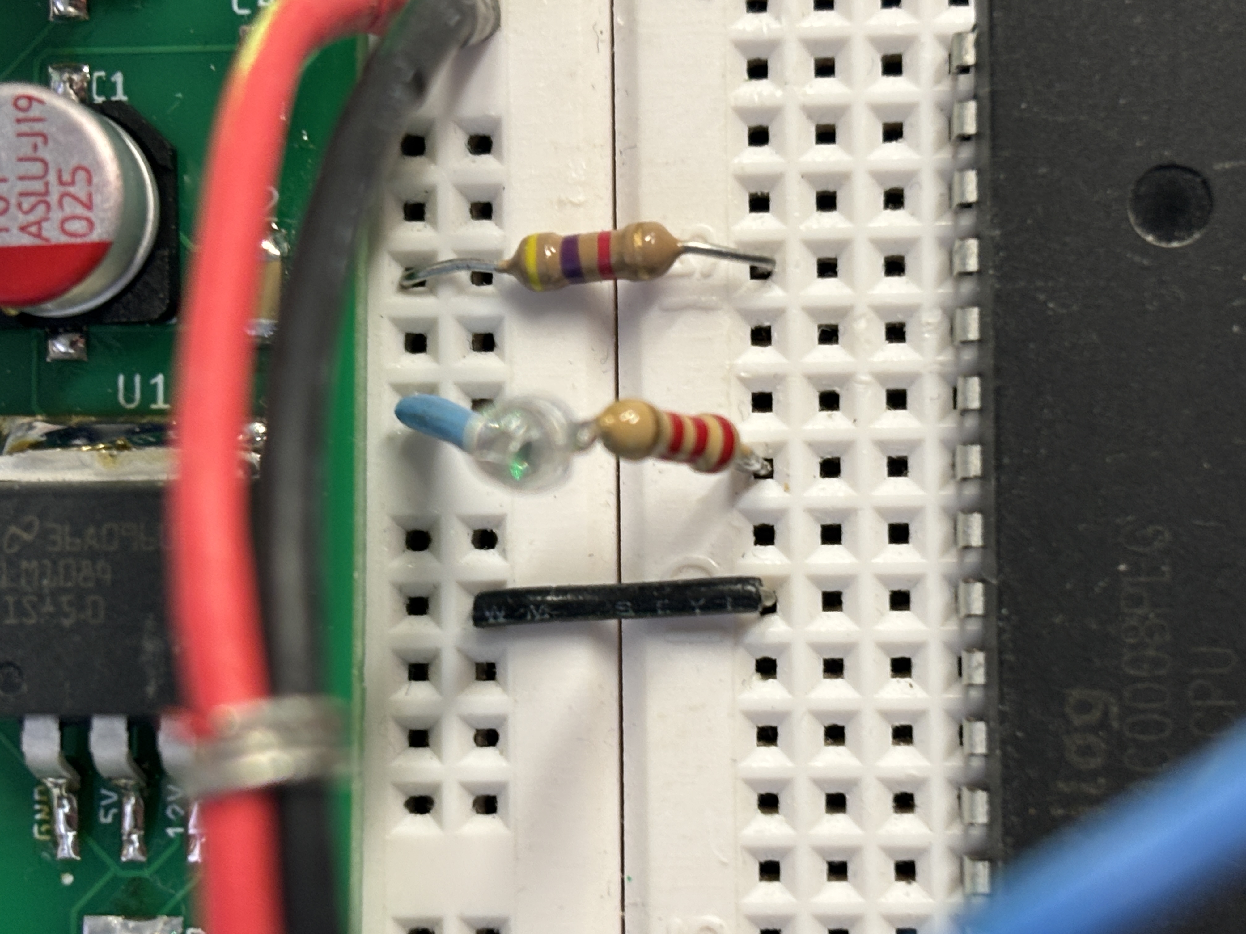
(Click to enlarge) Observations: You may notice that there are about 3 or 4 clock flashes before the M1 LED flashes, then another 3 clock and one M1, followed by another 3 clock and one M1. (The entire instruction cycle can be 4 or 5 or 6 for M1 and 3 or 4 or 5 for M2 and M3.) Does it sound complicated? The number of clock cycles is dependent on the instruction and if it requires a source data byte and destination data byte. The M1 LED flashing proves to us our system is working. If your system is not working, put a 4.7K resistor on the Z80's pin 24 as shown in the right-most photo below and connect it to the 5v rail. This WAIT signal should not be left floating which we have just corrected. More info on WAIT later.
Clock In (left) and M1 out (center) 4.7K Pull Up Resistor on Pin 24 (WAIT)
(Click the .gif file above to see the .mp4 video)
|
![]()
Updated 2025-11-27