|
Z80 Build From Scratch |
|
|
PAGE 17: PPI & LCD Panel |
|
|
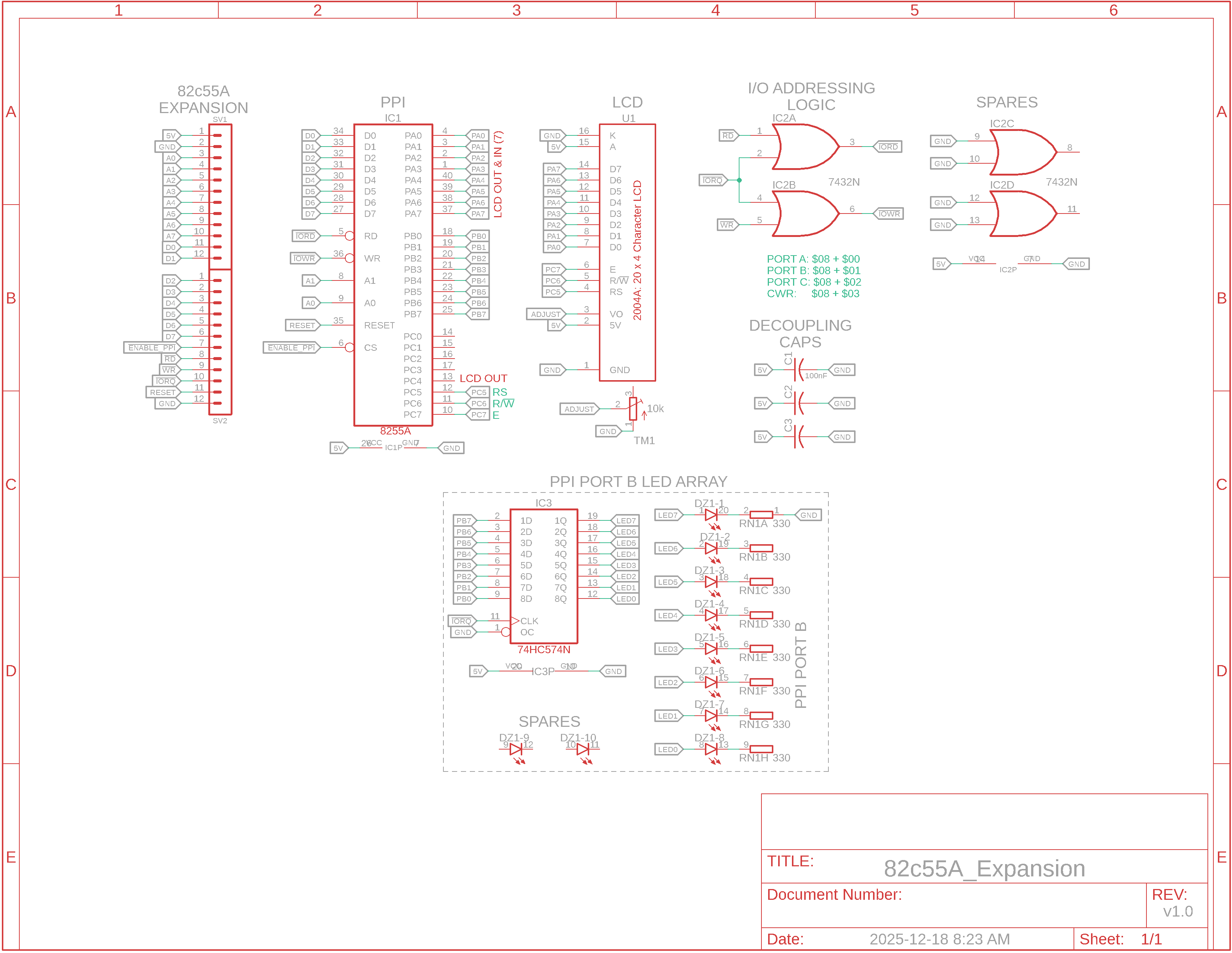
Instead of just LED bar graphs we are going to use a PPI to connect to a parallel LCD panel as well. We'll use all of Port A to send display data to the LCD and one-half of Port C (Port C High: pins 4 to 7) to control the LCD using E, RW and RS pins. (We won't need Port C Low pins 0 to 3 and one of the Port C High pins, pin 4.)
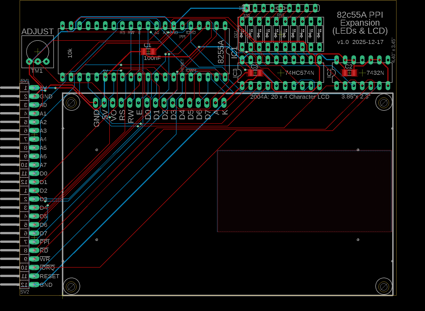
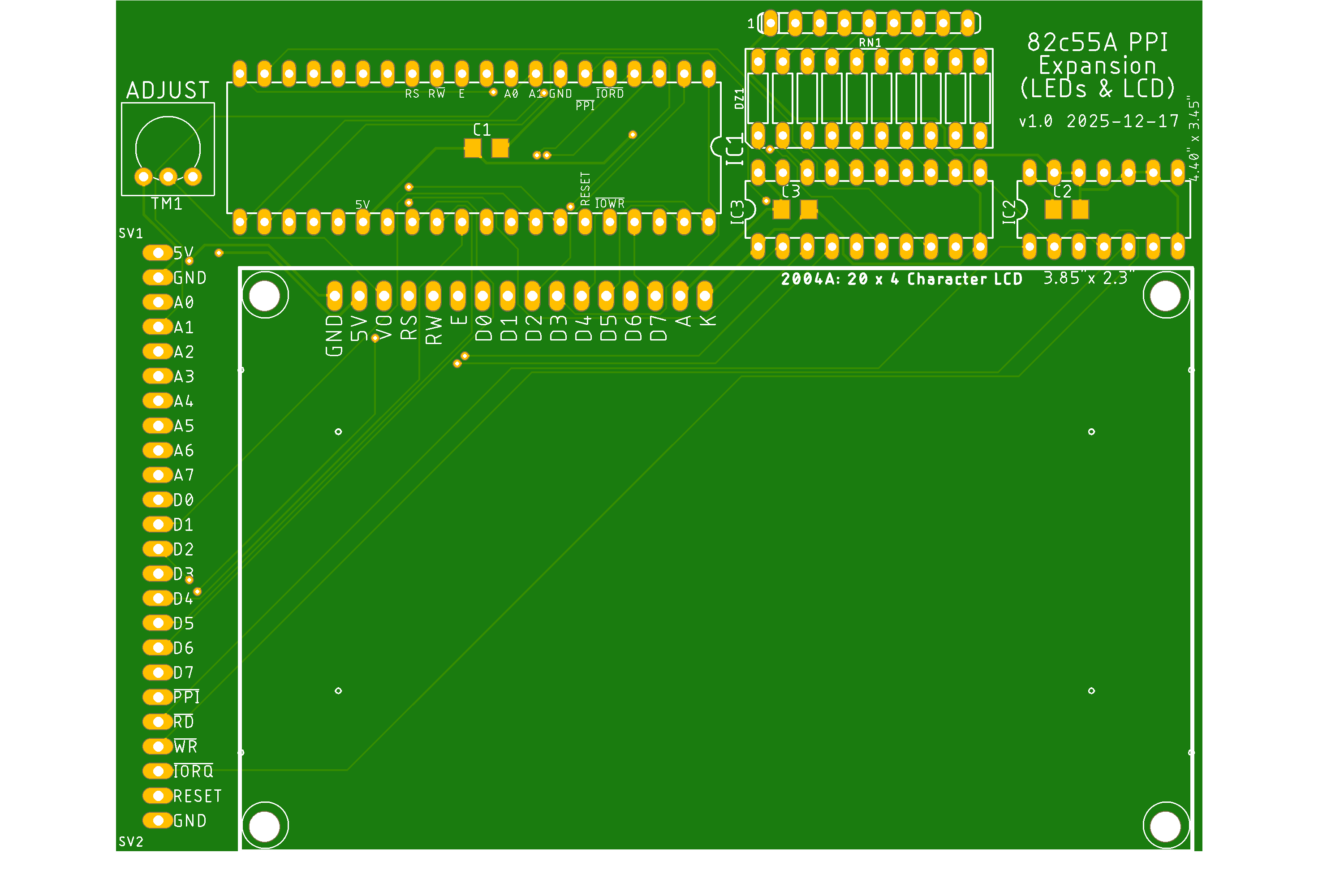
PPI Expansion Board v1.0 Schematic Diagrams
How It Works: The CPU's data bus is connected to the PPI's D0 to D7 for input data. One of the data pins, D7, can be used by the 8255 PA7 to poll the LCD panel to see if it's busy.
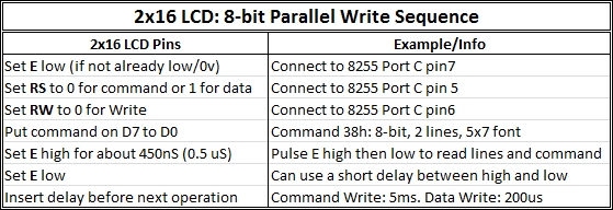
The adjacent LCD Write Operation chart shows the order of operations to output characters to the LCD. Essentially it indicates the 3 control lines from the 8255 must be asserted before a control or data byte from the PPI is sent to the LCD. To have the control lines and byte read/latched by the LCD, the LCD Enable line is pulsed high then low.
R/W is set to Write mode (0) as data is always sent from the microprocessor (CPU) to the LCD module and not in the opposite direction. The Read mode (1) can be used to determine if the LCD is busy. RS is the Register Select pin. It allows the LCD module to decide if data coming from the CPU must be interpreted as an LCD command (RS low) , or if it must be treated as text data (RS high) to be displayed on the LCD screen. E enables LCD access for each CPU-to-LCD transaction. As soon as a communication starts from the CPU side, this pin must be set high to enable the LCD. On some LCD display controllers, you need to pulse this line low after pulsing it high. On others, it returns to low level once the procedure is completed. We're going to pulse it high, delay a moment and then pulse it low for the most common LCD panels/controllers.
Summary of Operation In summary, we set R/W low to Write, RS low for a Command or high for Data, send the Command or Data on D0-D7, and pulse E high then low to read/latch the 2 control lines and 8 data lines. To avoid the complexity of using the busy-check function, we'll add a little delay during the Enable pulse.
|
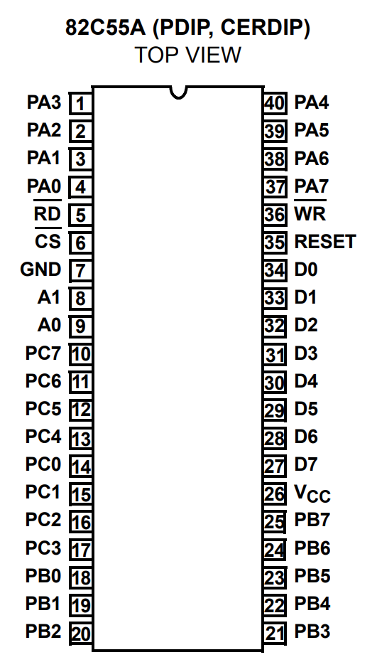
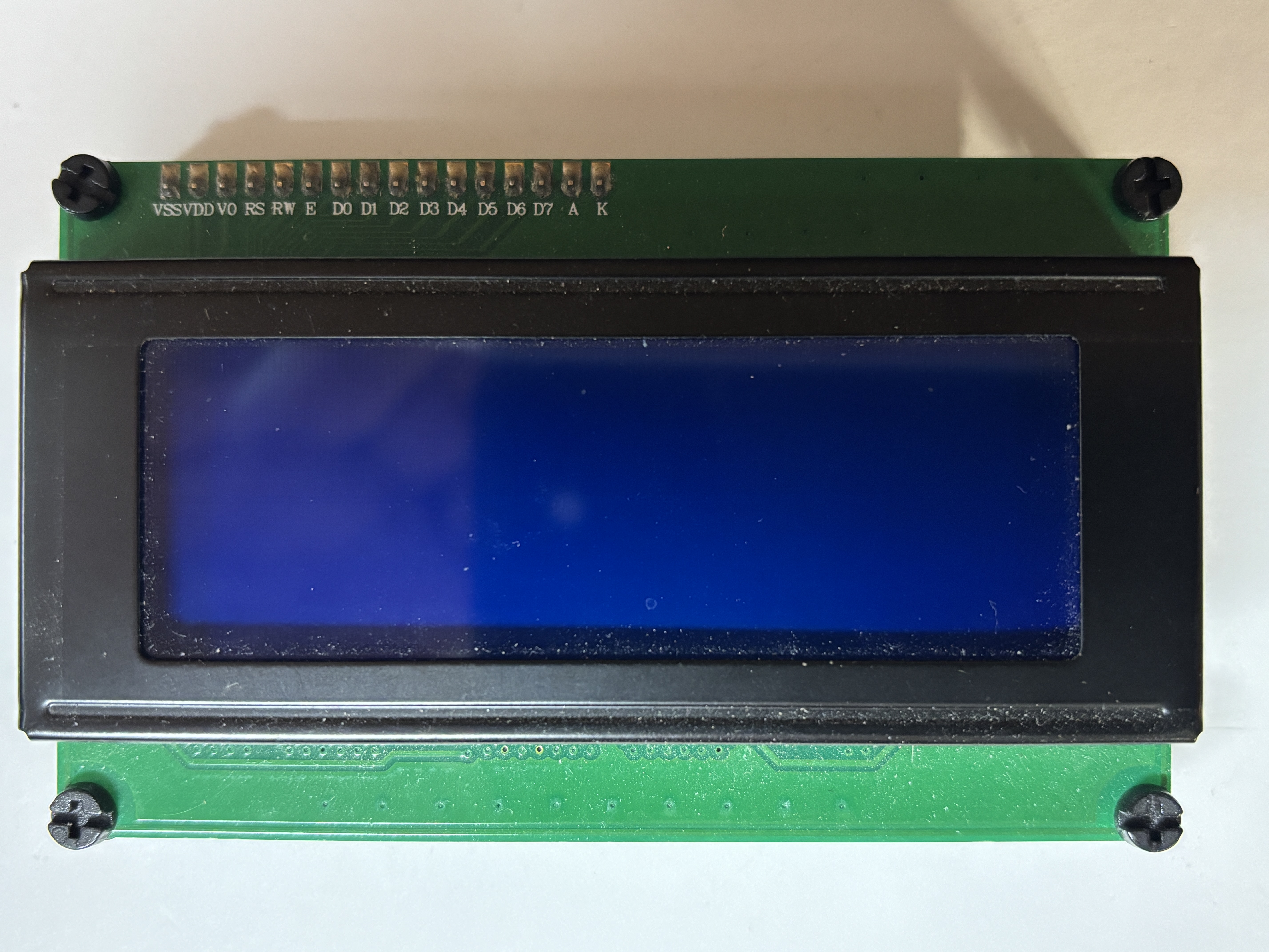
82c55a Pinout, 2004A Parallel LCD Panel (Click to enlarge)
16x2 LCD Pinout
LCD Write Operation
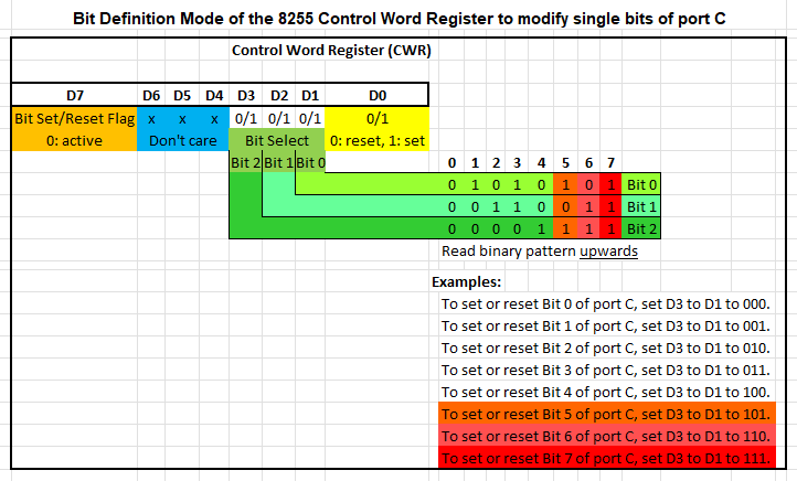
LCD Configuration: Bit Definition Modes
|


![]()
![]()
Updated 2026-01-10