|
Z80 Build From Scratch |
|
|
PAGE 16: PPI Overview & LEDs |
|
|
82c55A PPI Overview:
The
82C55A Programmable Peripheral
Interface (PPI) is a highly versatile and popular integrated
circuit, often used to bridge the gap between a microprocessor (CPU)
and external peripheral devices like keyboards, displays, or A/D and
D/A converters.
It features 24 programmable I/O lines, organized into three 8-bit ports: Port A (PA), Port B (PB), and Port C (PC). Port C can be split into two 4-bit ports and can be combined with either Port A or Port B to form 12-bit ports if needed. We will combine Port B and Port C High to drive an LCD panel.
The 82C55A offers flexibility through three primary operating modes: - Mode 0 for simple input/output operations without handshaking - Mode 1 for strobed I/O with handshaking signals to synchronize data transfer between devices of different speeds
-
Mode 2
which configures Port A for bidirectional bus communication. For the LED bar graph display we'll use the simple Mode 0 operation.
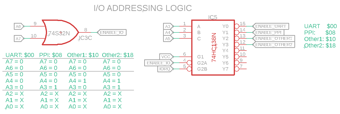
We discussed using the 74138 back on Page 11 to select our I/O devices. Address $00 is used by the UART, address $08 will be used by the PPI, etc. I/O Addressing Logic (Click to enlarge)
To address each PPI port individually, addresses with a base of $08 will be assigned. As an example Port A will be $08, Port B will be $08 + $01 or $09, Port C will be $08 + $02 or $0A, and the CWRCfg configuration register will be $08 + $03 or $0B.
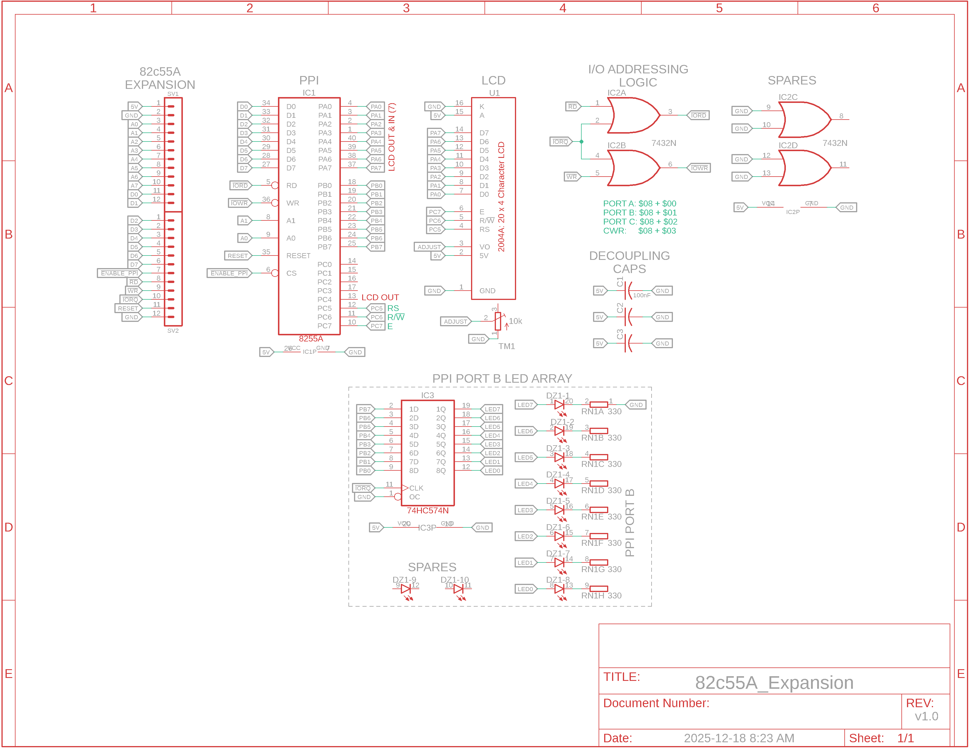
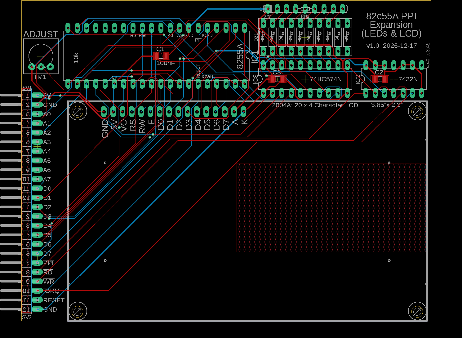
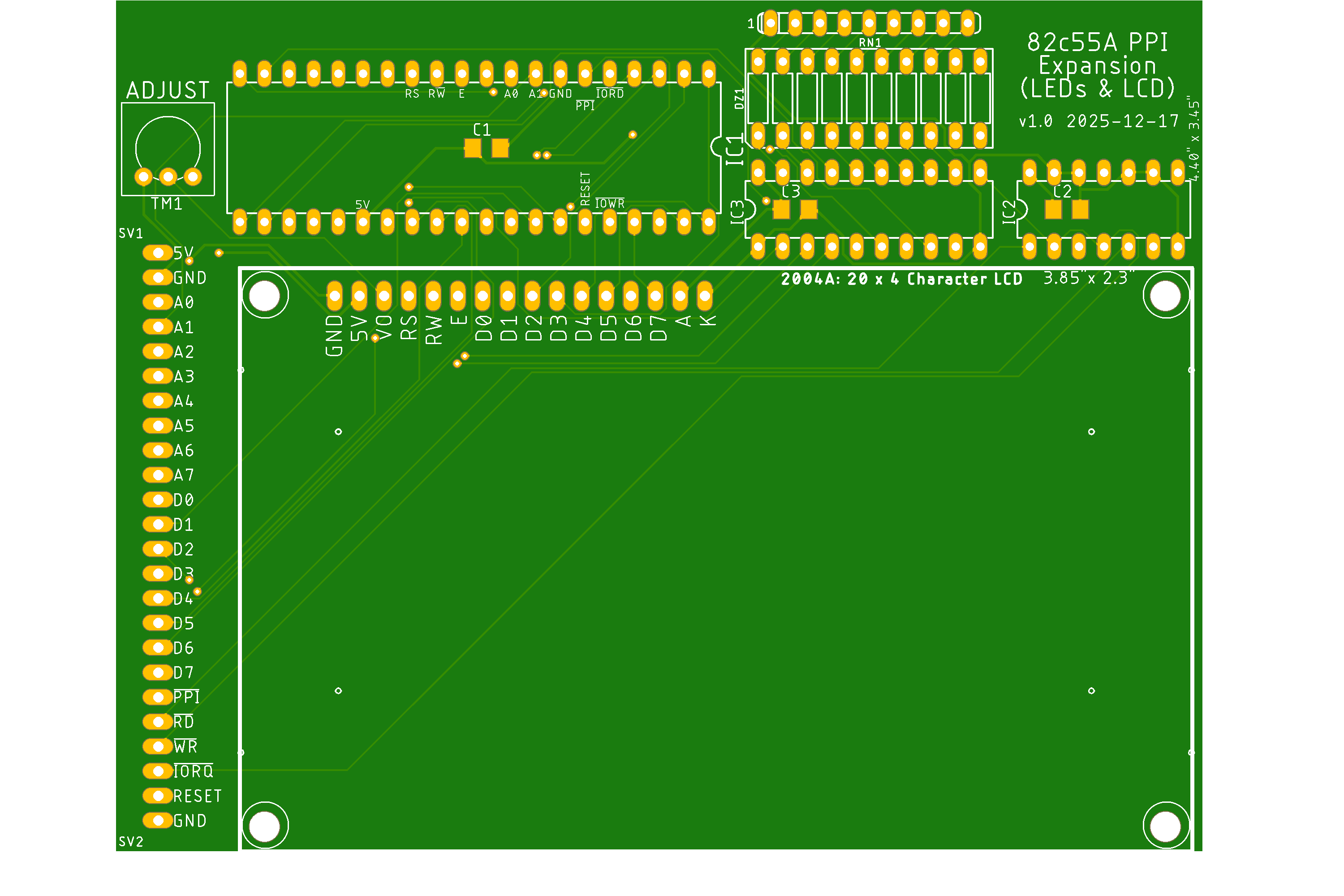
82c55A Expansion Board Below are the schematics and board design for expansion of our Z80 UART system to include a PCB containing the PPI and two circuits. The circuits are a LED bar graph and a 4x20 LCD panel, which we'll look at later. You may also notice the expansion port now has provisions for attaching the Z80 base system to this PPI or to two other boards, one at a time. If the system proves successful we can always redesign for a Z80 base system attached to a buffered backplane to other boards.
PPI Expansion (Click to enlarge)
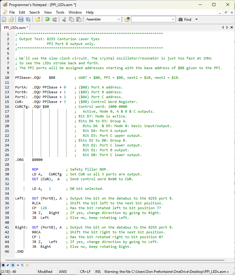
We're going to test the PPI by outputting data on Port B to a LED bar graph. Below is a screenshot of the PPI_LEDs.asm file you can view or you can open the code itself.
PPI_LEDs.asm (Click to enlarge)
|
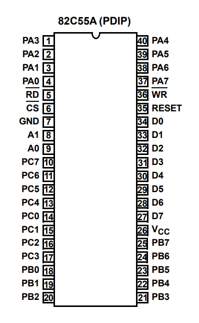
82C55A Pinout (Click to enlarge)
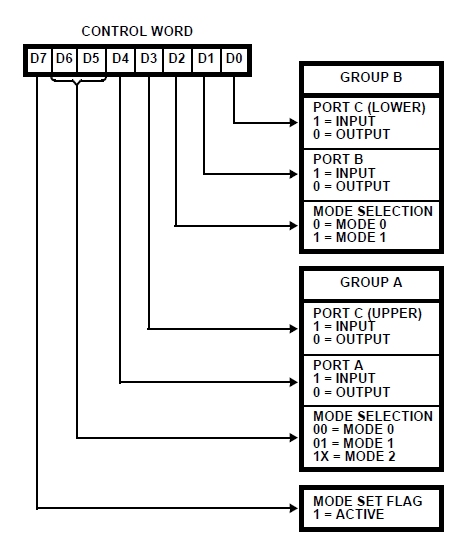
PPI Configuration Mode Definition Format for the Control Word Register (Click to enlarge)
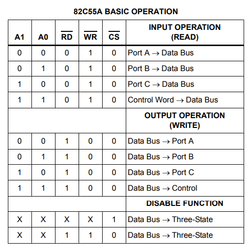
PPI Basic Operation (Click to enlarge)
Short Video Demo (Click to enlarge)
|
![]()
![]()
Updated 2026-01-10