|
Z80 Programming III-b |
|
TASM .asm, .lst, .bin Files |
|
Change it up
We're going to
change things up just a little.
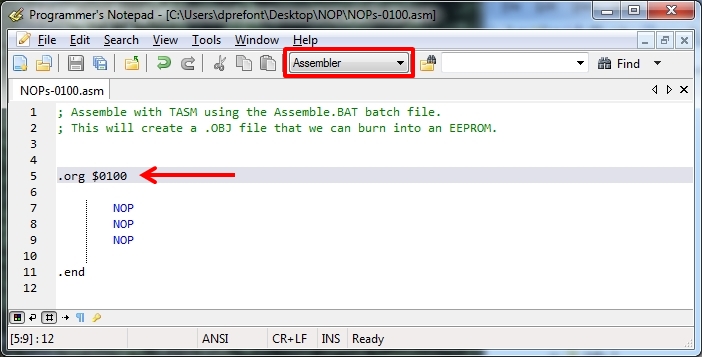
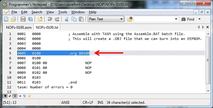
Within PN close everything but your .asm file. Ensure "Assembler" is showing as your file type in the drop-down box at the top of PN. Change the ".org $0000" statement to read ".org $0100"; only make that change, please. Now save it in the same NOPs folder on your desktop, as file NOPs-0100.asm. Compile the file using the TASM choice under Tools. These two adjacent screenshots below should be the results. In line 5 of the .lst file on the right, notice how the address is now $0100 and not $0000 any longer? That's because that is where the machine language will be written in memory when you burn the .bin file to an EEPROM. But how does the Z80 system know to ignore all of the data that may be at address $0000, $0001, etc. before it gets to address $0100? It doesn't. By default, most brand new EEPROMS will be programmed with $FF at every address unless they have already been used, in which case the leftover code will be there. Your Z80 may not perform as you expected; can you say "Crash and Burn"?
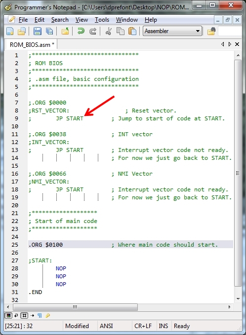
Jumping Ahead Close the files you've been working on with PN. Open the file ROM_BIOS.asm instead. In the left-most screenshot below, you will notice a lot of comments before you get to the code which appears the same. Earlier we mentioned that the Z80 will go to address $0000 at bootup or reset by default.
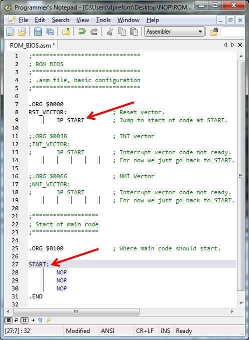
Our code starts at $0100. That means the CPU will try to run whatever is stored on the EEPROM between $0000 and $0100 with undesirable results. So we need to put some useful code between those addresses and that is the purpose of "JP START" that has been commented out in the left screenshot of the two. In the right screenshot of the two, you can see the comment character ";" has been removed to reveal the assembly code. Let's read just the code in order of appearance starting at the top of the right screenshot. .ORG $0000 ; Start the program here. RST_VECTOR: ; This is a label for a location, $0000 in this case. JP START ; The "JP" or jump instruction tells the CPU to go to the label named START. This 3-byte instruction will reside at location $0000. Notice that START is placed after .ORG $0100. .ORG $0100 ; This tells the TASM assembler to start addressing the program at this location. Our first NOP instruction in line 28 will be at address $0100. START: ; This arbitrarily named label is where the program will start. This is the location the "JP" in line 9 points to. Because it is immediately after the ".ORG $0100", it will be at location $0100. NOP ; The first of 3 NOPs. The instructions are one byte wide so the first will be at $0100, the second at $0101, and the third at $0102. .END ; A directive to TASM to stop enumerating the source code and start assembling it into machine code.
Let's examine the assembled files
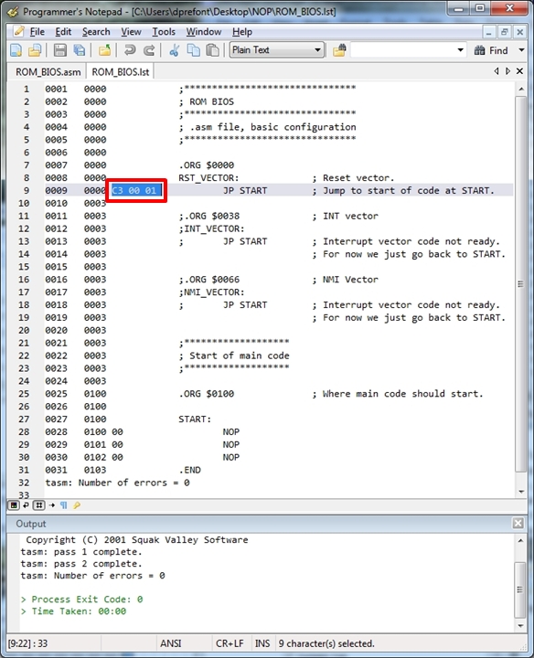
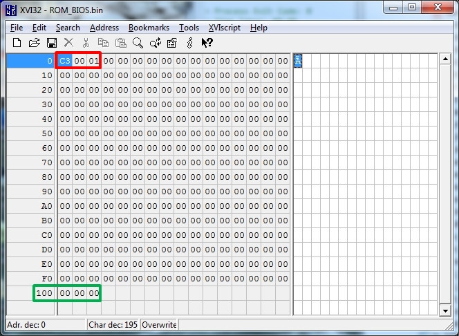
Let's have a look at both the .LST file and the .BIN file. According to page 262 of the Z80 CPU manual, "JP nn" is a 3-byte instruction: the first byte is "C3" followed by a 2-byte address. We should expect to see the machine language "C3 01 00" when we examine either the .LST or .BIN files, right? Unfortunately, no; we see "C3 00 01" instead. The Z80 CPU uses what is known as "Little Endian Byte Ordering". Yeah, it's a real thing just like "Little Endian Bit Ordering" is a real thing in Ethernet: the least significant bit in any byte to be transmitted is put on the wire first, followed by the next, etc. Not confusing at all is this data stuff? But this is LEBO not LEbO, so for address "0100" the low order byte "00" is stored first followed by the high order byte "01". We expect to see the following in the program and in ROM storage: "C3 00 01". Is that what you're seeing below highlighted in red in the two screenshots? The ".ORG $0100" states that what follows will be addressed starting at $0100. We can see that in the .BIN file screenshot: there are three bytes of "00" at address $100 highlighted in green. Remember the "-c -f00" switches we added to the PN tool for TASM a while back? Their job was to fill all of the locations up to the assembler's ".END" directive with zeroes, and that's what you're seeing in the XVI32 screenshot. It will be the same on the EEPROM we program.
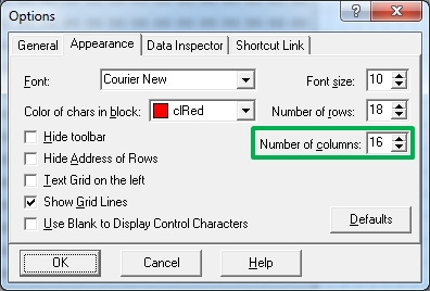
Looking closer Some of you looking at the XVI32 screenshot above are noticing the address locations seem different from yours. Your second line starts with "11" and not "10" as in the one above. That's because I "corrected" the XVI32 display to match what most decompilers and network analysis tools will show - 16 bytes per row. Here is the change you need to make under XVI32 | Tools | Options | Appearance if you want to follow my example.
|
