|
CIRCUITS 2: UART Serial Comm |
| Resources (click to enlarge) |
Serial Communication: 16C550 UART |
|
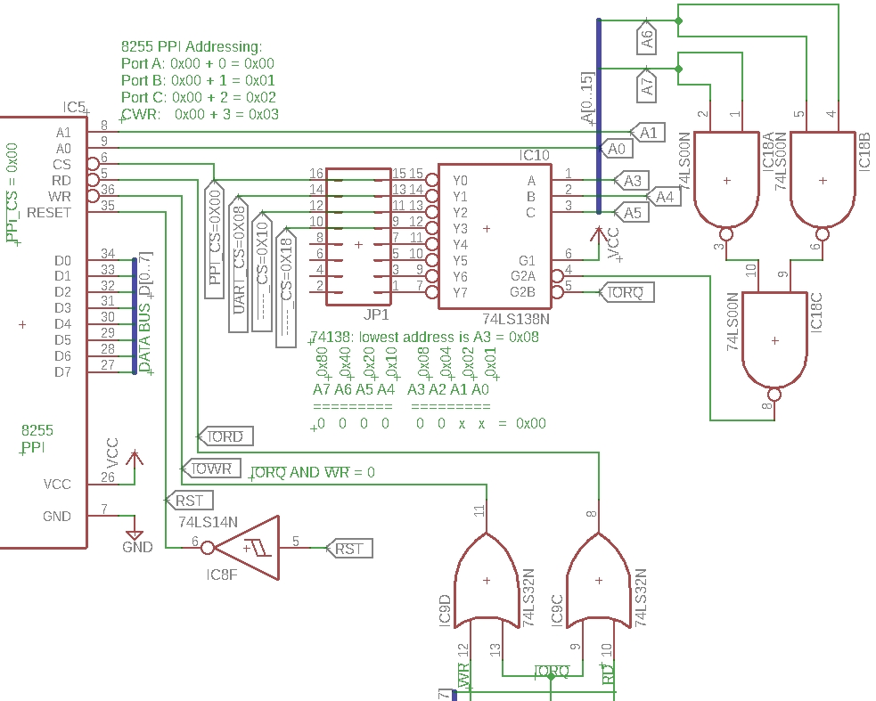
Eagle CAD: 74138 Addressing Scheme
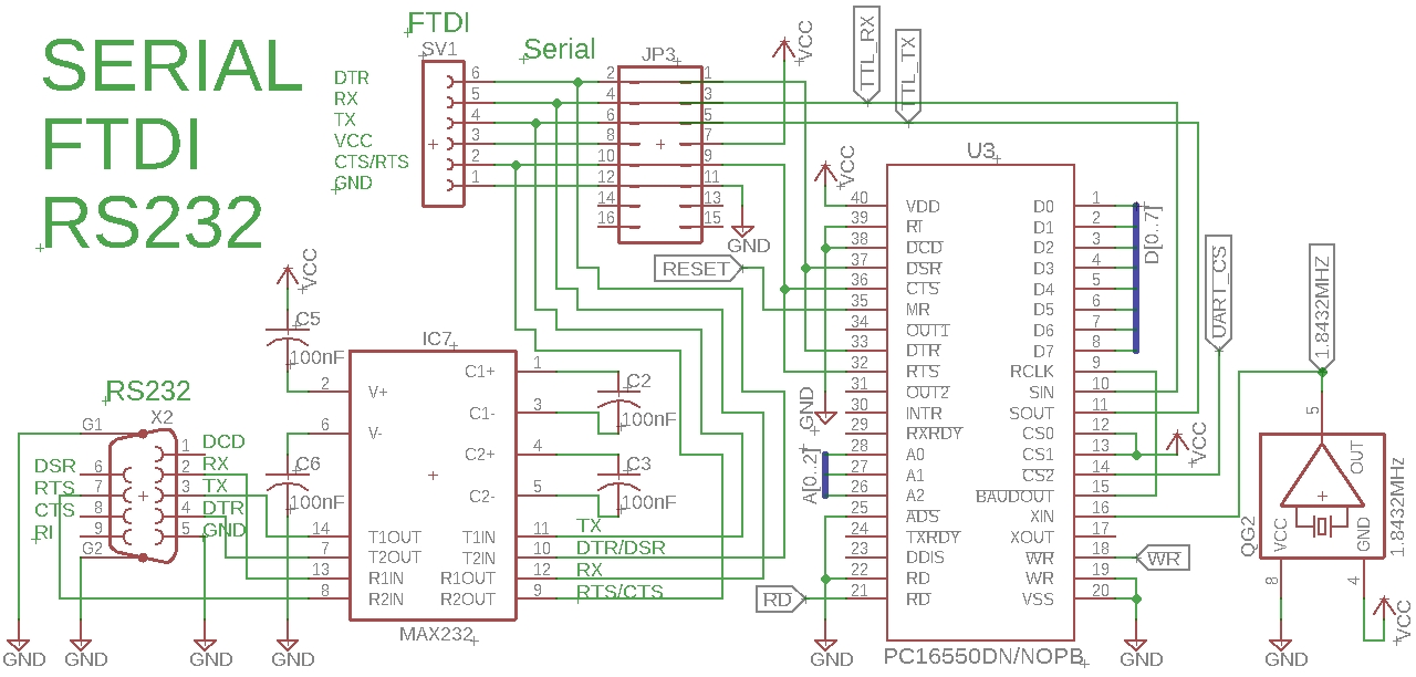
Eagle CAD: 16550D UART Schematic
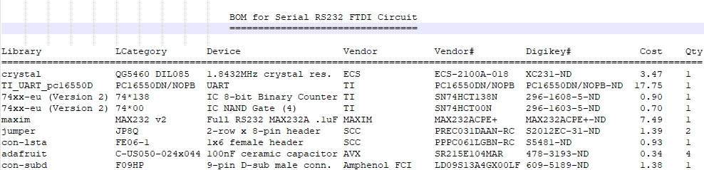
(Bill of Materials)
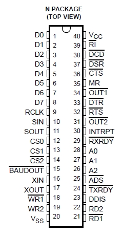
16C550 (DIP40) UART Pinout Diagram
16C550 (PLCC44) UART Pinout Diagram
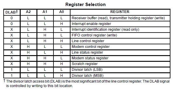
16550 UART Register Selection
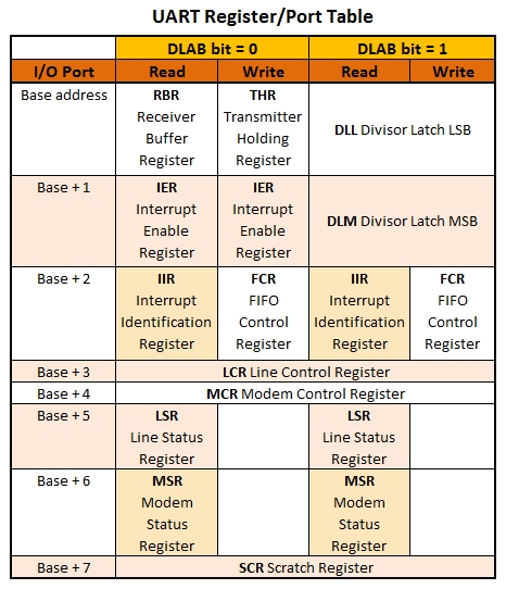
UART Register to Port Conversion Table
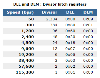
Divisor Latch Registers
LCR: Line Control Register
LSR: Line Status Register
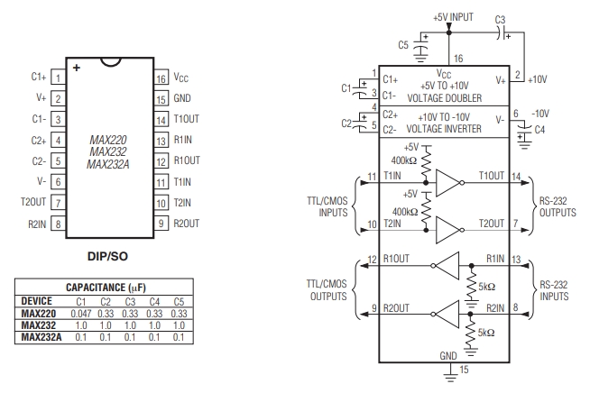
MAX232A RS232 Transceiver Pinout Diagram
|
Overview Our serial communication circuit will use the TI pc16550D UART and the MAX232A RS232 Driver/Receiver. We'll also provide 6-pin female connectors so a USB/FTDI serial adaptor can be used as well as a serial-over-Bluetooth adaptor. Only one or the other should be used at any one time. In our tests we won't connect the MAX232A and D-sub 9 connector, just the USB/FTDI circuit.
Tiny History on 8-bit UARTs and the Z80 First the 8250, then the 16540, then the 16550. That's enough history.
74138 Addressing Change The addressing we setup for the 8255 PPI did not support the easy addition of other devices. To do so means having sequential address lines for the 74138's A-B-C lines. We changed the address organization of the 74138 so multiples of 0x08 will now be used. (A0=1, A1=2, A2=4, A3=8, A4=$10, etc.) With 256 I/O addresses available, using a multiple of 8 addresses for each device means we can now address 32 devices, each having up to 8 individual addresses. Examine the upper schematic, 74138 Addressing Scheme. - PPI_CS address is $00 - UART_CS address is $08 - Third device address is $10 - Fourth device address is $18 - Etc.
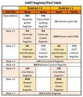
16550 UART There are 12 registers in the UART as shown left in 2 charts (16550 UART Register Selection, UART Register to Port Conversion Table). Both charts indicate the port value to be added to your base IO address for the device. Example: we used $00 as the base address for the 8255 PPI. We'll use $08 as the base address for the UART (UARTbase EQU $08). If we wish to send an OUT command to the Line Control Register (LCR), we'll need to send it to the base address plus 3: $08 + $03 = $0B. Our code uses EQU statements to equate a label with the register so we don't have to remember the numeric address. We could equate address $0B to "LCR" or "UART_LCR" or "UART_R3" or whatever. NOTE: The 16550D UART Schematic has the oscillator pins mislabeled: GND should be 4 and VCC should be 8.
Size Matters Well, it does when it comes to PCBs. The smaller the footprint of devices like the UART, the better. The DIP package uses 2 rows of 20 lines. The PLCC chip socket or carrier uses 4 x 11 pinout so it takes up a lot less space on your PCB. It's not suited for breadboards unless you use a PLCC44-DIP40 adaptor. Be advised that you can buy a package of 8 adaptors on eBay for a little more than you would pay for one adaptor. Maybe they're not the same quality but that will depend on how often you'll use it.
Connecting the UART to a Driver/Receiver Device The UART output will be TTL-level TxD (transmit data) and its input will be TTL-level RxD (receive data). To be RS232 compatible, we'll attach a level converter device to take the 0v (low) and 5v (high) TTL levels to become RS232 Standard signal voltages of +3v to +25v (low) level and -3v to -25v (high) level. (Check out this link for additional information on the RS232 standard.) Originally, getting the TTL signals to RS232 level was a two chip function using both a 1488 driver and 1489 receiver as well as separate +12v and -12v power supply lines. Today we can minimize the chip, component, and power supply line counts by using a single voltage supply with the MAX232A that supports 0.1uF decoupling-type caps. The adjacent bottom diagram, MAX232A Transceiver Pinout, shows the connections and cap selection.
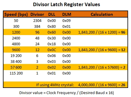
Configuring the UART Initial configuration of the UART is to specify the baud rate (its communication speed), followed by the data formatting. We'll stick with the very common format of 8N1 or 8-bits data, No parity, and 1 Stop bit. Using a 1.8432MHz crystal oscillator, we can divide the signal down to various baud rates. For a speed of 1200bps, the Divisor is 96 (1,843,200 /16 /96 = 1200). We need to place that value (hex 0x60) in the Least Significant Byte of the Divisor Latch, the DLL. According to the adjacent Divisor Latch Registers table, 0x00 should be placed in the Most Significant Byte of the Divisor Latch, DLM, for the baud rate, 1200bps. So the 16-bit value should be 0x0060 spread between two 8-bit registers, DLM and DLL.
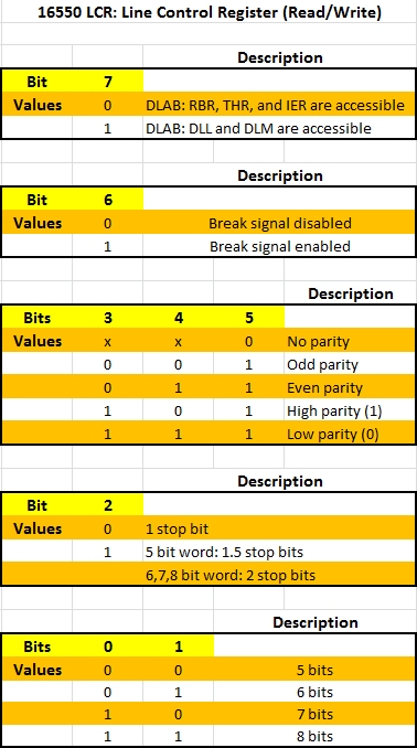
In the LCR, Line Control Register, bit 7 has a special name and purpose. It is called the DLAB bit or Divisor Latch Access Bit. Initially during configuration, it is set to a 1 so that the DLL and DLM (both mentioned above) can be used to set the baud rate. Once the baud rate config is completed, the DLAB is set to a 0 so the Tx and Rx buffers can be used to move an internal byte to external bits, or the reverse action of assembling external bits to an internal byte.
UART Registers If we configure the UART to have a base address of 0x08, here is the configuration we'll need that is taken from the assembly file RS232-Terminal-Echo-Test:
UARTbase EQU 08h ;
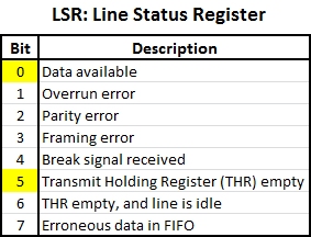
UART Initialization Steps 1) Set DLAB to 1. 2) Set DLL and DLM to 1200bps using a divisor of $0060. 3) Set byte framing to 8N1, reset DLAB to 0. 4) Check LCR bit 0 to see if receiver Data Ready Indicator is set to a 1 when a complete incoming character is received from the bitstream and transferred to the RBR (Receive Buffer Register). This is a READ operation from what was formerly the DLL but is now the receiving buffer. 5) Get the incoming character from the UART. 6) Check LCR bit 5 to see if the THRE (Transmitter Holding Register Empty) indicator is set to a 1 indicating the UART is ready to send the byte as a bit stream. This is a WRITE operation from what was the DLM but is now the sending buffer. 7) Send the outgoing character to the UART.
As you can see starting in lines 41 to 82 of the assembled file, RS232-Terminal-Echo-Test.asm, there are only 3 code blocks in order to perform a terminal echo test: - Initialize the UART - Get a character from the UART - Send a character to the UART
Testing Visit RS232 Tests to test your circuit. It contains useful info and a video demo.
Z80 Assembly Language Programming Visit Z80 Programming V to learn how the Assembly code works for this circuit. Also visit Z80 Programming VI to learn how the Assembly code works for this circuit
|
