|
ZB64EC-bus Z80 UART Comm Bd. |
| PCB Circuit (click to enlarge) | Circuits and Info |
|
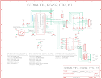
Eagle CAD: 1. UART Comm Bd.
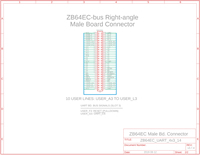
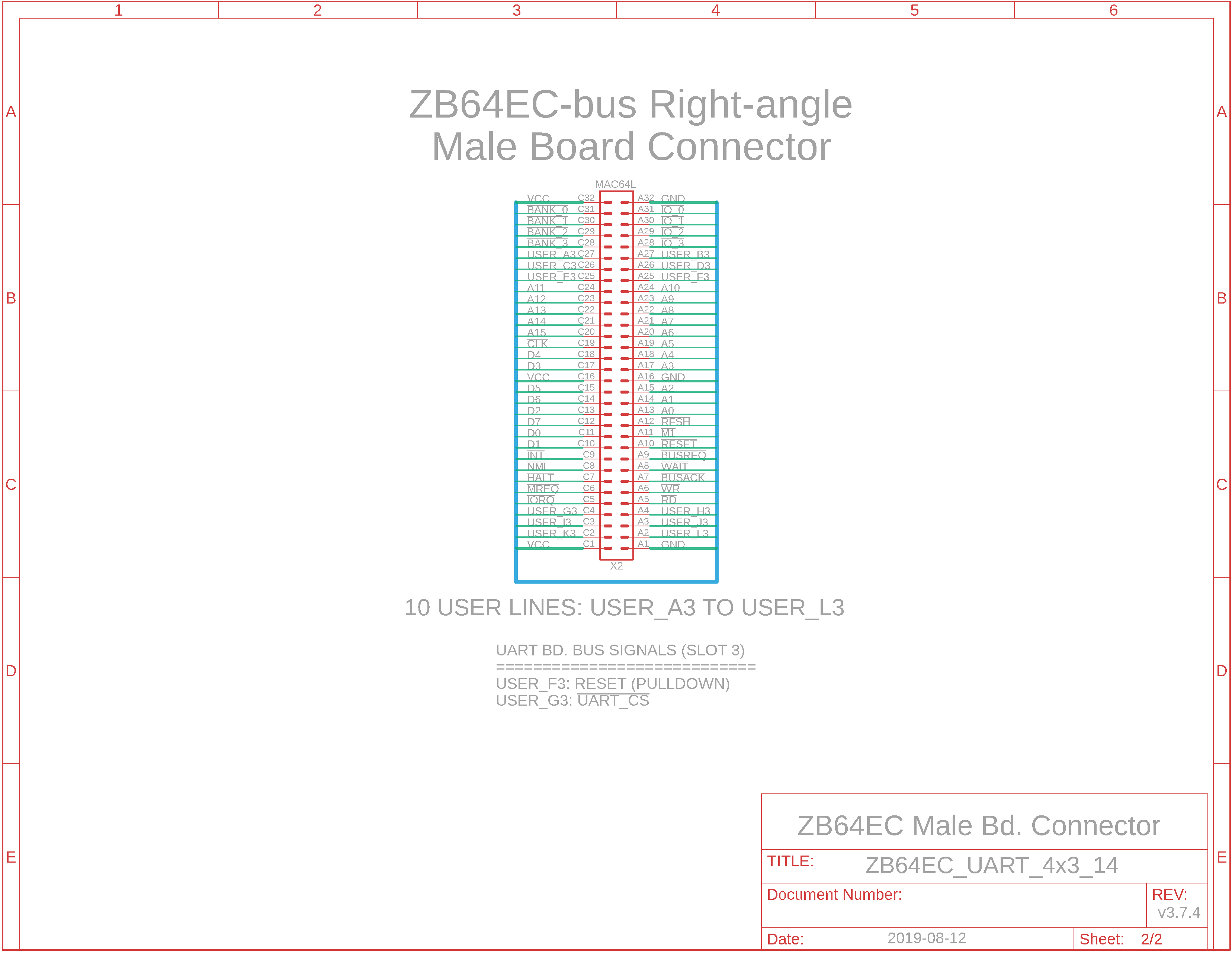
Eagle CAD: 2. EC Board Connector
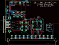
Eagle CAD: 3. Possible PCB Layout
Bill of Materials |
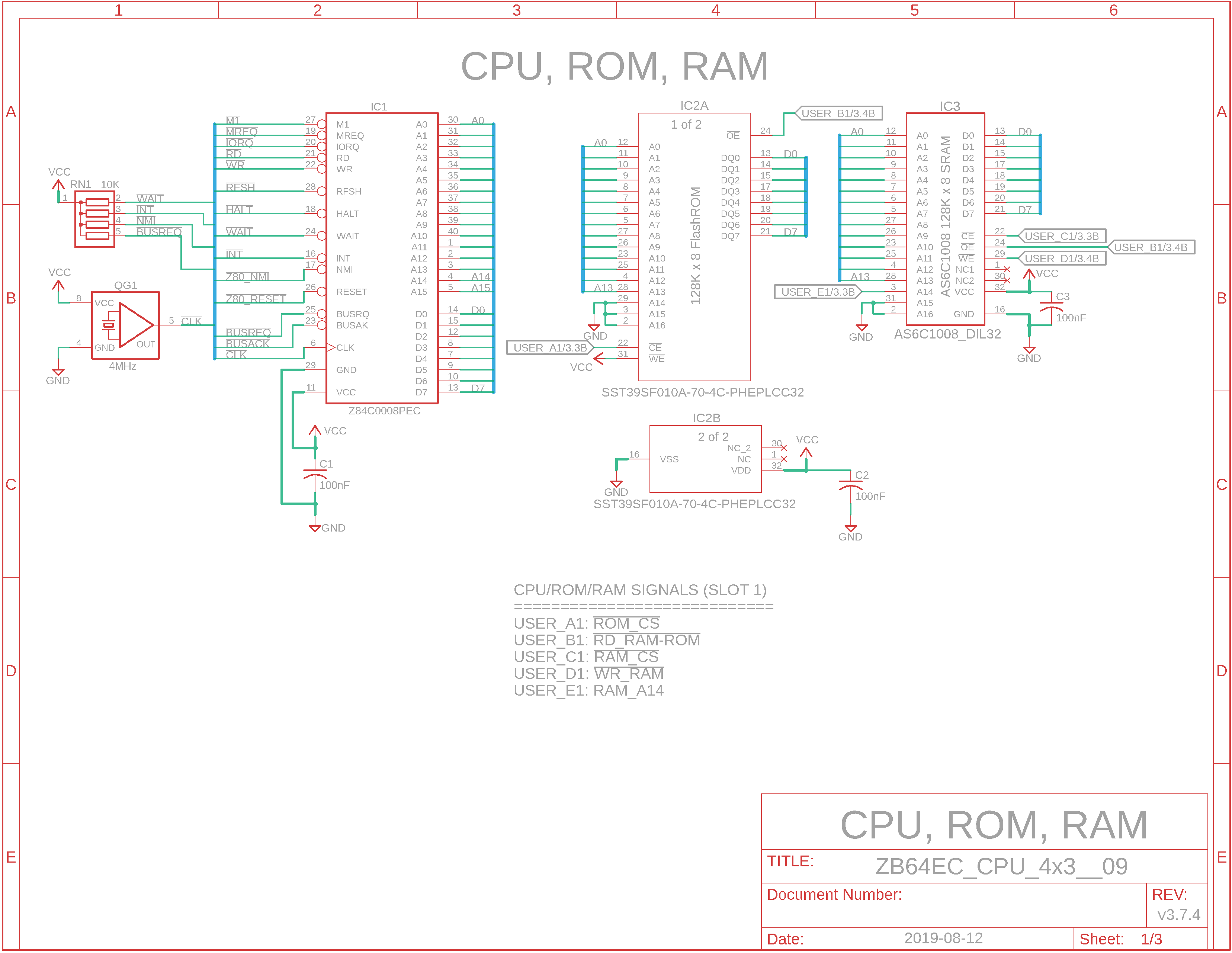
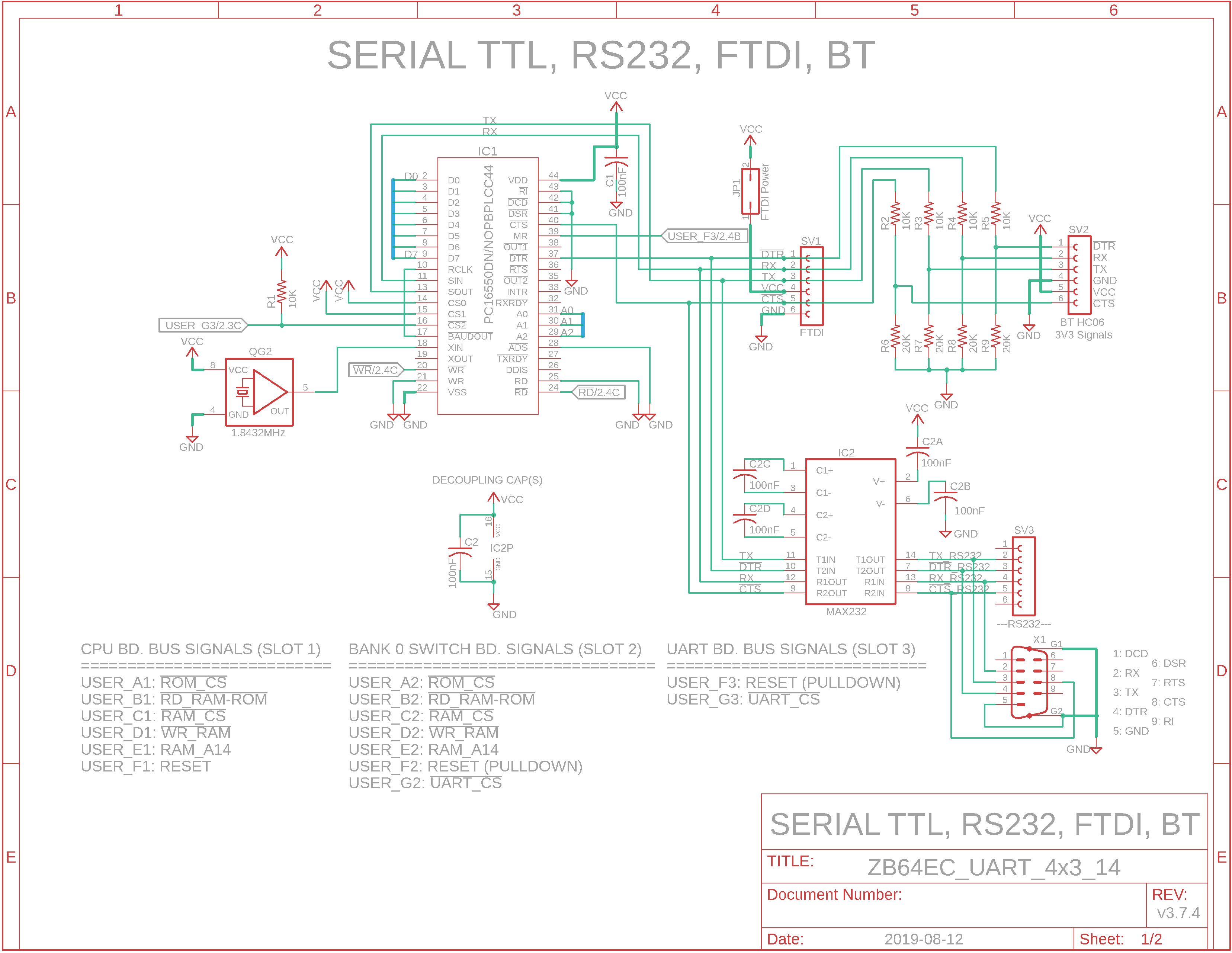
System Overview The basic ZB64EC Z80 system is modular and is composed of 4 boards: - an extendable 6-slot backplane - a CPU/ROM/RAM board - a Bank0 ROM-RAM switch board - a UART board for terminal communcation: USB/FTDI, RS232/Bluetooth, and RS232 D-sub
Additional boards can be added to the system, including a bus extension board. See the ZB64EC-bus Z80 MBC menu for the current list.
UART Bd. Features There are 3 ways to communicate with your multi-board computer via a PC terminal: - FTDI/USB - RS232 Serial jumper block - RS232 Serial 9-pin D-sub connector It is strongly recommended you only use one at a time with your TeraTerm PC terminal emulation software. A power jumper (JP1) for the FTDI/USB connector can disconnect power to the interface if you choose to use one of the other interfaces. Many of the Bluetooth adaptors need 3v3 and not 5v, hence the reason for the 10K/20K resistor network used at SV2.
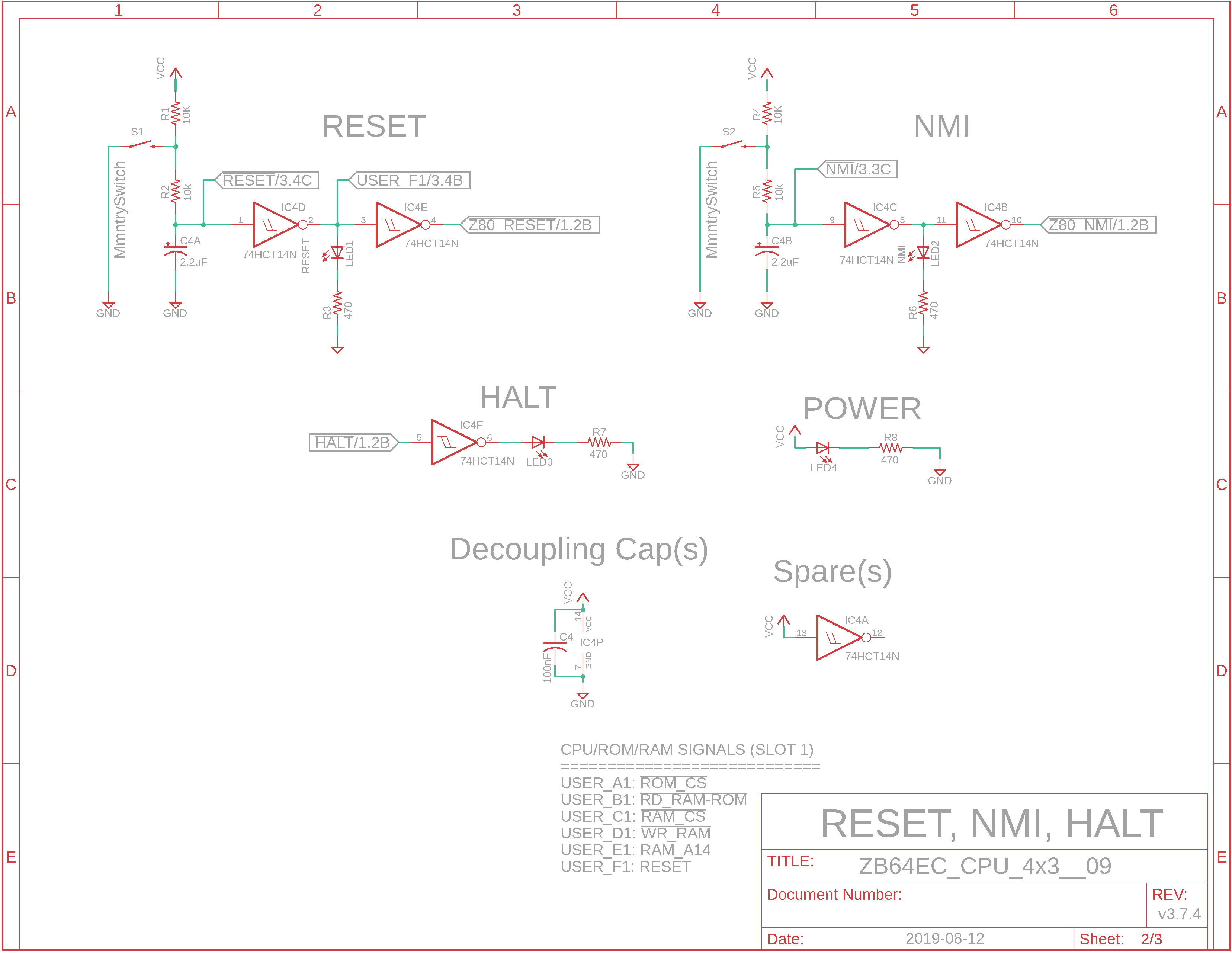
USER_x Bus Lines Each bus line is available at each slot via jumpers. It is possible to use a single bus line across the backplane many times for different functions. The second adjacent screenshot lists the User lines for Slot 1 and Slot 2 of the system. An example of carrying a signal from slot to slot would be the RESET signal of USER_F1. This is not the Z80_RESET signal used by the Z80 CPU; this is a separate positive-going signal used by the UART's MR on pin 39 of the UART Comm board that will most likely occupy Slot 3. The USER_F1 signal will need to be jumpered to USER_F2 and then to USER_F3 in slot 3. If you examine the second adjacent screenshot, Eagle CAD: 2. EC Board Connector, we have listed the connections that will be needed to be made to the CPU board in Slot 1: - USER_F1 to USER_F2 to USER_F3 - USER_G1 to USER_G2 to USER_G3 If you suspect stability issues with the UART's Master Reset line (pin 39), you can tie the USER_Fx line to GND via the pulldown resistors in Slot 6. Of course, you will need to jumper USER_F1 across the backplane to USER_F6 if you decide to use the pulldown resistor.
I see the schematics. Where is the Bill of Materials parts list? The BOM is at the bottom of the adjacent panel.
Note: M62 Bus is copyrighted by Peter Murray of Murray Electronics, http://www.39k.ca |
|
|
|
![]()