|
Z80 Build From Scratch |
| PAGE 12: UART Config |
|
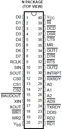
UART (Universal Asynchronous Receiver Transmitter): There are a few different UARTs we could use for serial communication but we have had good success with the PC16550DN device. Which is more than can be said for the WDC65c51 ACIA that had a transmit bug. The UART will take our bytes, turn then into bits and them send them sequentially out any attached interface to our PC via a USB RS232/FTDI adaptor. While looking at the UART pinout diagram below we noticed pin 35 is Master Reset, MR, but it's active high whereas the Z80 CPU MR is active low. To the right of the pinout diagram we have changed our schematic to include two spare 7414 inverter/NOT gates to accommodate both the CPU and UART: the first NOT gate connects to the UART and the second NOT gate connects to the CPU. When the reset switch is pressed the UART is reset as is the CPU.
UART Pinout, Reset Circuit
(Click to enlarge) UART Configuration: Setting up the UART takes a few steps due to the complexity and flexibility of its internals. Our initial config will address most of the functions shown in the block diagram below.
PC16550DN Block Diagram
(Click to enlarge)
|

![]()
Updated 2025-12-08