|
Project 48: |
|
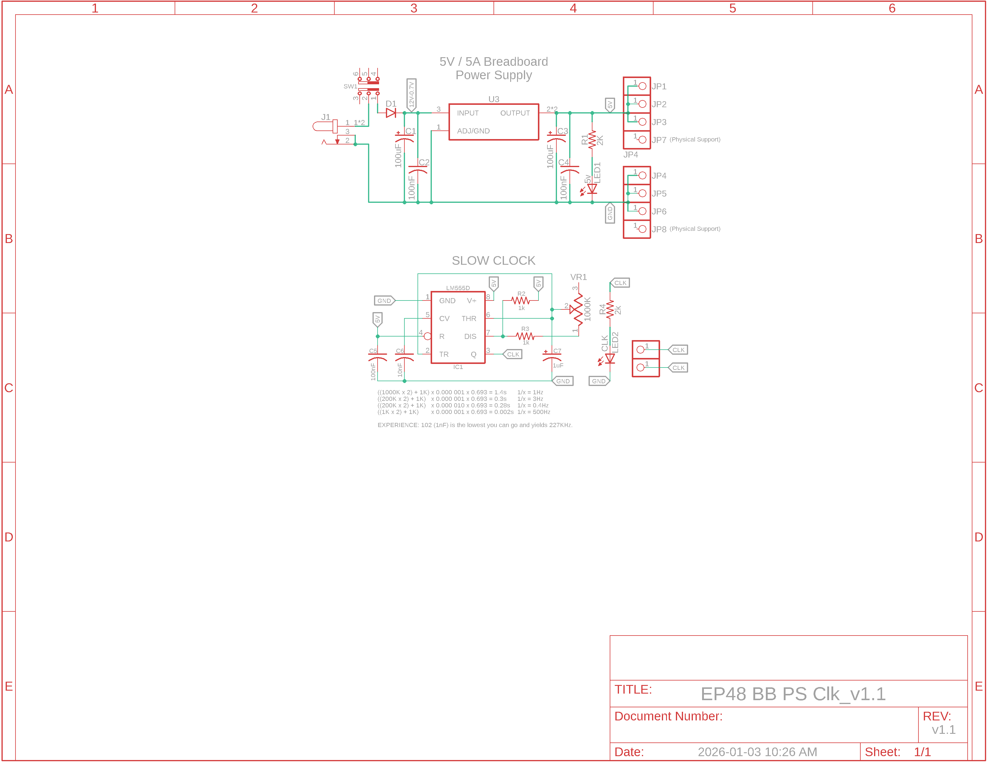
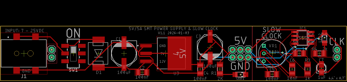
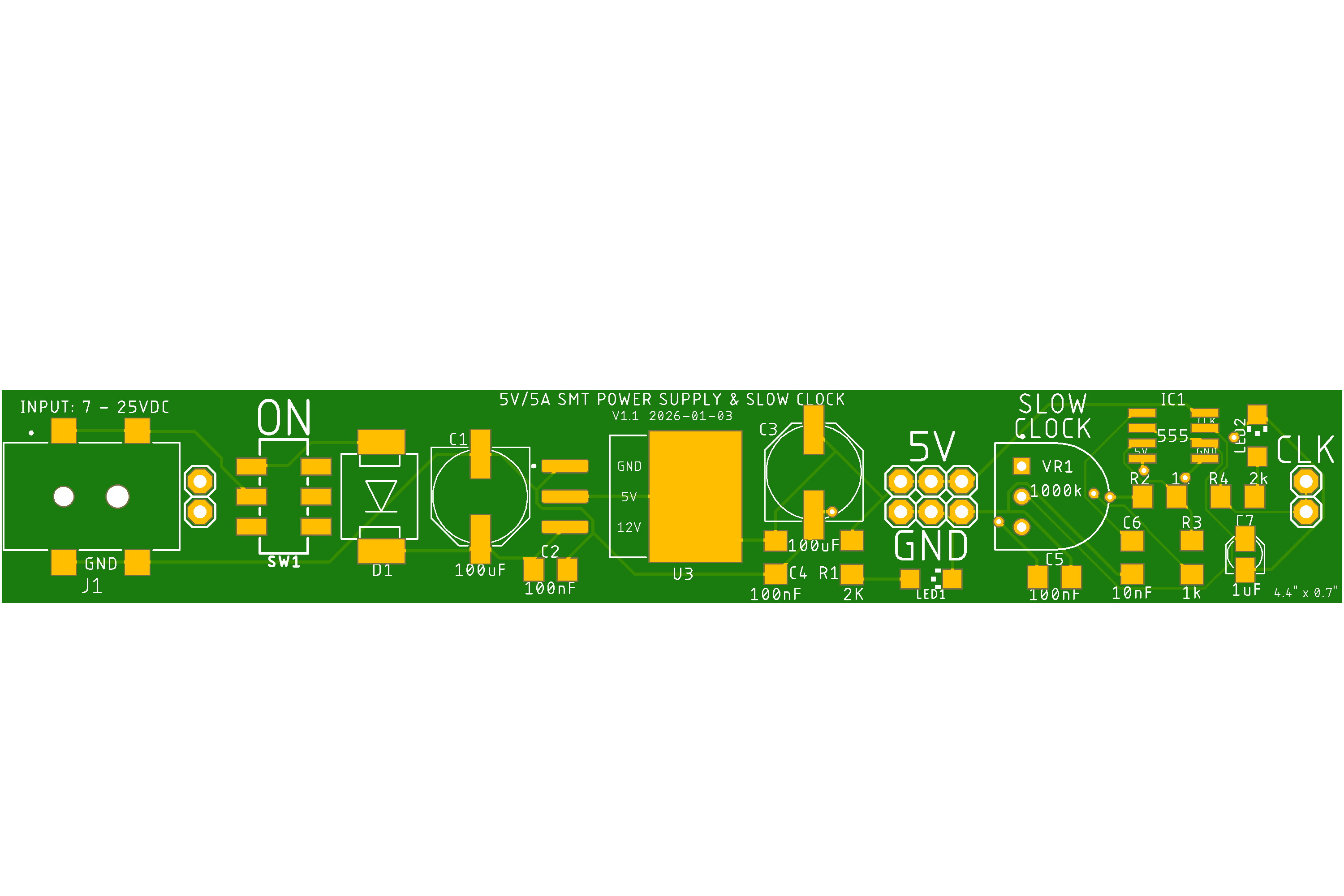
v1.3 Schematic, Board Layout, PCB Top & Bottom (Click to enlarge)
v1.3 BOM
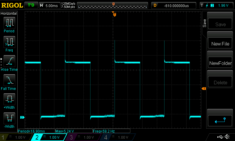
O'scope Photo
Overview: A breadboard PCB power supply and slow clock for project development.
Features PS: - Input 7v to 25v DC, 2.5mm jack, polarity protection - 5v/5A output - On/Off switch - breadboard alignment pins on input and middle of PCB
Slow Clock: - Adjust speed via a potentiometer. - If you use a female header at position C7, then the range becomes variable: 1Hz to 500Hz with a 1uF cap, 7Hz to 5kHz with 100nF cap - Above we see a 59Hz square wave
|

Updated 2026-10-07