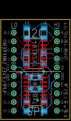
| I2C Voltage Level Shifter v1.0 | |
|
Pix/Vids/Schematics click to enlarge) |
Info |
|
Eagle CAD Drawing v1.0
Eagle CAD PCB Layout v1.0
Results of Running SDInfo.ino
Eagle CAD: v1.0 Bill of Materials
|
Description: This voltage level shifter allows you to use modern 3.3v peripherals with older 5v microcontrollers. Actually, the voltage choices are up to you and are only limited by the TI TXS0104 (I2C) chip.
Details: The PCB contains the TXS0104 (4 pins) that are used for I2C and its open collectors. All four 5v pins have been pulled high with 10k resistors. Combined with the internal 10k pullups, that gives us a strong 5k pullup. Plug the level-shifter board into the center of your breadboard (BB). Wire the 3v3 pin to one BB rail, the 5v pin to another rail and the GND pin to a common ground.
Example Usage: I2C example: A-HI on the HIGH side connects to SDA from the 5v Uno or Nano, and A-LO on the LOW side connects to SDA of a 3v3 peripheral like an SSD1306 1.3" OLED display
References: Phillips app note AN97055: bi-directional level shifter for I2C-bus and other systems. Texas Instruments also has a guide on level shifters.
Pix: In the left panel you can see pix of the PCB that was sent out for manufacture. The v1.0 PCBs returned, one was populated, defluxed and tested with I2C-Scanner.ino and SPI_SD_ListFiles.ino. The results of the I2C Scanner program show the I2C addresses of the BME280 sensor. Below are 2 enlargeable screenshots from my Rigol oscilloscope. The signals from the I2C device look pretty good without much signal ringing or overshoot. No pullup resistors were added to the BME280 or OLED devices. They will be present however when the v1.6 PCBs return from fab.
|
+
Updated 2024-11-26 @ 8am


