|
Project 3: |
|
Schematic, Board Layout, Top & Bottom PCB
v1.0 Video of Operation
Gerber files have been sent out to JLCPCB.com for fabrication.
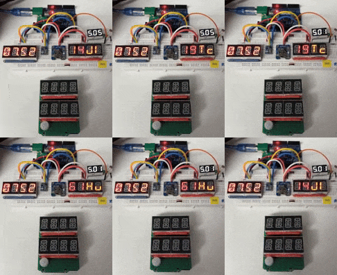
Description: In this project two 14-segment quad LED "tubes" are used to show time and sensor data. An Arduino UNO R3 shield has been extended laterally and vertically by 0.3" which allows room for the two tubes. On the underside of the shield we find a PCF8523 RTC as well as an AHT10 temperature/humidity sensor. Several holes have been drilled to provide airflow to the sensor. On the topside of the shield is a motion PIR and LED, as well as a light-sensing LDR.
Parts: Quad Alphanumeric Display, 0.54" digits with I2C Backpack: https://www.adafruit.com/product/1911 PCF8523 Real Time Clock breakout board: https://www.adafruit.com/product/3295 AHT10 Temperature/Humidity sensor breakout board: banggood.com LDR photoresistor: Adafruit Product161
Code: Sketch name is UNO_RTC_AHT10_HT16K33.ino. Libraries include Adafruit_GFX.h, Adafruit_LEDBackpack.h, Adafruit_AHT10.h, and RTClib.h.
|
Updated 2025-08-05


